


Building a Raspberry Pi to Capture ADS-B signals
Picking apples, pears, blackberries or raspberries
In a previous blog post, I provided a very high-level overview of ADS-B, and that with the appropriate pieces of hardware and some open-source software, it was possible to capture and decode the radio signals being broadcast from commercial aircraft, with the view to tracking these aircraft in near real-time (and providing a high-volume of streaming data at the same time).From the title of this blog post, one may ask “Do you have to use a Raspberry Pi?” To which the answer is unequivocally “Absolutely not!”
I chose the Raspberry Pi (RPI) for two very important reasons:
- It is (relatively) cheap (~£35 GBP / $45 USD)
- It is made in Wales, UK (my home country!)
However, as mentioned in the project overview blog post, I wanted to ensure that anyone who wanted to take part in this project could do so. One way of achieving this, was to ensure we chose hardware and software that were not going to break the bank!
A few other questions I addressed included:
- If you intended to build one of these flight tracking devices, would it be operational 24×7? If so, using the laptop that you carry around with you from home to office would not be the best choice.
- I have a spare HPE DL380 lying around, can I use this? Sure you can – but probably a waste of resources!
- Would you be considering making your streaming data available to organisations such as Flight Radar 24 (www.fligthradar24.com)? This will be discussed in more detail later.
- As some of the software components of this project require Linux, it seemed to make sense to keep everything in this project the same (or as close as possible). Taking note that Linux (CentOS in this example) is “free” (and Windows is not).
- Are you concerned about the power consumption of running your flight tracking device 24×7? For reference, a rough calculation of running a headless RPI is at worse, £12 ($16) per year (that includes a 70% inefficiency loss of converting 240V AC to 5V DC!)
Which Raspberry Pi?
With so many to types (Model A, B and Zero) and generations (Model A: Gen 1, 1+, Model B: Gen 1, 1+, 2, 2 ver 1.2 and 3 etc) to choose from, it may seem difficult to decide on a selection.With the exception of the RPI Zero (of which I have no experience in using), if you are going out today to buy your first RPI, as they all cost about the same, try to pick the highest generation (model). At the time of writing this blog post (October 2017), the latest RPI is the Raspberry Pi 3 (i.e. Model B: Gen 3).
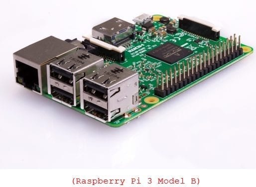
The high-level specification of this model is:
- CPU: 1.2 GHz 64-bit quad-core ARM Cortex-A53
- 1GB RAM
- On-board wireless LAN (802.11n) and Bluetooth 4.1
- 4x USB 2 ports
- HDMI
- Ethernet port
- Micro SD card slot
When I first started this project in 2013, I was using the Model B: Gen 1 RPI. This was powered by the 700 MHz single core ARM11 processor, had half the memory of the Gen 3 (512 MB), 2x USB ports and did not have on-board WiFi or Bluetooth.
This model worked perfectly well when I first started out with the antenna as described below.
In 2016, I upgraded to the higher specification RPI 3. The reason for this upgrade was a result of replacing the original antenna with one of a much higher specification. As a result, I was now receiving even more frequent messages from even more aircraft. With the lower specification Gen 1 RPI, it was observed that the single-core CPU was constantly running at 100%.
The replacement 4-core and double the memory RPI 3, is more than capable of supporting the even higher specification antenna.
What else do you need for the RPI?
Typically, when you buy an RPI, that is all you get (just like in the picture above). Unfortunately, you will need a few other bits ‘n pieces to get the RPI to work.However, you may find that you already have most (if not all) of the other components.
Power Supply (required)
The Raspberry Pi requires a 2A microB 5V USB power supply.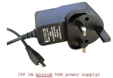
You can purchase one specifically for your RPI.
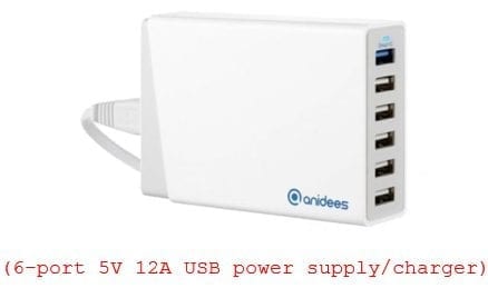
If you plan on running more than one RPI and/or multiple peripherals (e.g. external USB HDD), rather than opting for multiple individual power supplies, you may wish to buy a more powerful, multi-port power supply.
The example below is a 60W USB charger providing 6x 5V USB ports to a total of 12A.
With a power supply such as this, you will also need the USB cables from the charger to the RPI.
SD Card (required)
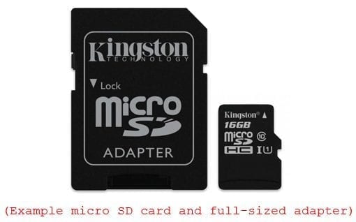
The RPI has no on-board storage (other than RAM). By default, the operating system (discussed later) is installed on an SD card which is plugged into the RPI.Depending on which RPI you have bought will dictate which physical size of SD card you require (full-sized or micro).
Obviously the greater the storage capacity and faster the card can read/write the better. However, an 8GB card is more than adequate to get started.
Unless you buy an SD card that already has the operating system pre-installed (this is an option), you will need to copy/burn the OS onto the memory card before it can be used in the RPI.
Most people chose to do this from another machine (laptop/desktop) running either Windows or Linux (noting my comment on MACs above). If this is how you are going to setup your SD card, you may need to check:
- Does your laptop/desktop have an SD card reader/writer?
- Do you need an adaptor (required if your laptop/desktop has a full-sized reader/writer, but your RPI requires a micro SD card) – see image below
HDMI cable, monitor/TV, keyboard and mouse
After your RPI is set up as a flight-tracking server, most people chose to operate it in headless mode – that is, without a screen, keyboard and mouse.In headless mode, your RPI will be connected to your network/internet. This enables you to connect to your RPI from other machines using terminal emulation software (e.g. PuTTY), telnet, VNC etc.
However, when setting up the RPI for the first time (and possibly subsequently in the event of problems), you will need to be able to connect to it, a display, and communicate with it via a keyboard and mouse.
If you plan on running your RPI in headless mode, then you may be able to “borrow” a HDMI cable, monitor/TV, USB keyboard and USB mouse from somewhere (or someone) else.
If you intend to keep the RPI “fully connected” (or you are not able to borrow these components), then you have no option other than to buy them.
Ethernet (RJ45) cable (optional)
The later RPI models are equipped with on-board WiFi (and Bluetooth), and those that are not can have WiFi enabled by attaching a suitable USB device.This gives you the option of connecting your RPI to your network via either WiFi or wired.
If your RPI is close enough to a network connection point (and you have spare network sockets), the preferred method of connection is wired. This requires less effort to set up, and provides for faster and more reliable data transfer.
Additional Storage
Depending on the storage capacity of your SD card, you may wish to add further storage to your RPI.If we exclude NFS (which is also an option), the only connectivity options for storage are via the on-board USB2 sockets. This obviously restricts the I/O speed, but let’s not forget, this is but a RPI!
Typical options may include USB memory sticks and external USB HDD.
In the example above, in addition to the 8GB SD card (which contains the operating system), there is a 2TB external USB drive (though noting an unpowered external USB drive will require additional power to that which the RPI can provide – although there is a really neat trick to get around this, which I will cover in a later post. )
Whether you need to have additional storage is totally dependent on what you plan to do with your RPI.
In summary, you may choose to retain a copy of all of the captured ADS-B data on the RPI as a backup (noting that if you follow this project through to completion, your data will also be in Apache Kafka and a Vertica database). You may of course also choose to use your RPI for other projects. After all, it is a computer that can multi-task!
If you have included an additional storage device, you may also decide to use this for the majority of the I/O on the RPI. This will save using the SD card, which typically have a shorter life expectancy when used for a heavy I/O workload.
Case of an RPI becoming a RiP (learn by my mistake!)
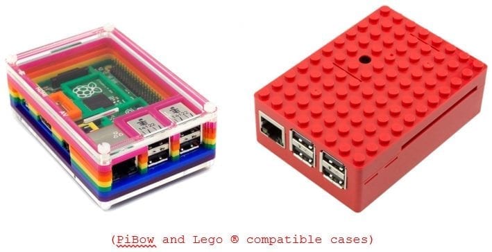
The RPI comes as a raw circuit point with all of its electrical components exposed. From a health & safety point of view, this is not a problem (other than maybe a slight scratch from the soldered connections or its 40x connector pins).However, if you do not want to give your RPI a current obituary and hope it will Rest in Peace (RiP), I would strongly urge you to protect your RPI in its own protective case.
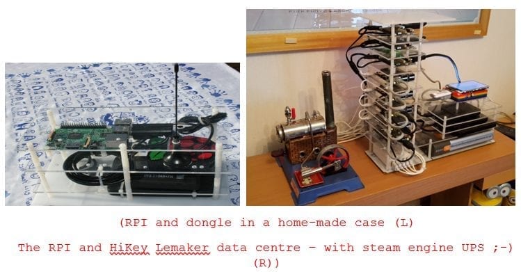
As you might expect, there are many to choose from. From plain clear Perspex through to the highly coloured PiBow and Lego® compatible boxes:
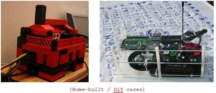
If you are so inclined, you could of course build your own (the first image below thanks to my grandchildren!):
ADS-B USB Dongle
Everything we have covered so far should be sufficient (from a hardware perspective) to get a fully-operational Raspberry Pi.The final piece of hardware is the digital broadcast receiver.
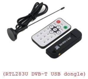
Although there are a number of options and suppliers of these devices, the one which I started out with (and is more than adequate for this project), is a RTL2832U+R820T DVB-T USB Digital TV Tuner (doesn’t slip off the tongue quite so easily).
Prices for this dongle vary considerably from ~£10-£25.
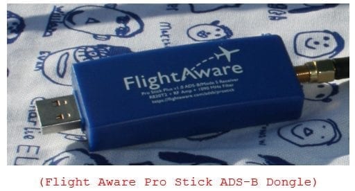
The second USB dongle I have experimented with is an ADS-B specific dongle. This includes a Radio Frequency Amplifier and 1090 MHz Filter (though I have yet to compare performance between this and the one above as 1/3 the cost).
As its name partially implies, the first device is typically used for watching terrestrial TV on your laptop or computer, maybe when away from home.
It just so happens that the chipset inside this USB dongle covers a much wider frequency range than is required to capture terrestrial TV signals. It also covers the frequency 1090 MHz – the frequency on which the ADS-B signals are broadcast from the aircraft transponders.
Size and Frequency Matters!
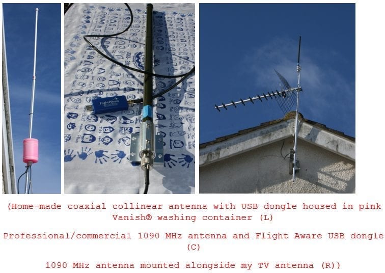
This 6” stubby antenna with its short cable is perfectly adequate for picking up strong signals from aircraft close to the receiver, and depending on the topology of the land around you, and the proximity of tall buildings and other structures, will typically pick up signals from a 50-70 mile radius of the receiver.If you want to increase the catchment area and pick up weaker signals and aircraft from further afield, you will need to invest in an antenna specifically designed for picking up the 1090 MHz frequency.
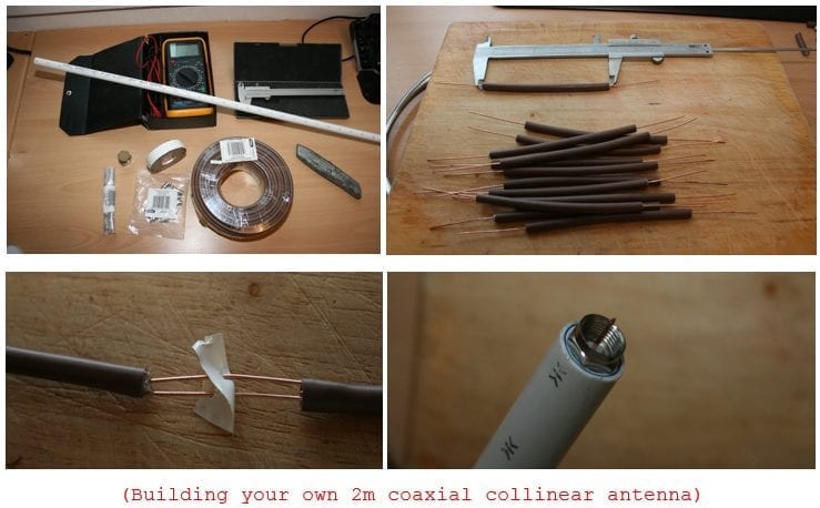
For this you have two options. Spend a serious amount of money on a commercially available one (noting that this will set you back 2x or possibly 3x the cost of the RPI!), or do as I first did – build your own!
Rather than clutter this blog post with how to build your own, you may wish to do as I first did – follow the instructions on a web site such has this: https://www.balarad.net/
In the meantime (and just in case anyone doubted I built my own), here are some pictures:
Pink Vanish container and plastic cable ties
With all our hardware gathered together, it’s time to assemble it.But before we do so, a couple of further considerations:
- For optimal performance and coverage, the antenna needs to have clear line-of-sight of the aircraft transmitting those ADS-B signals.
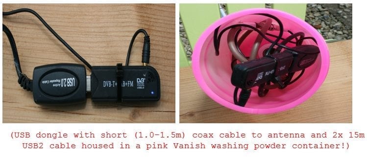
o To achieve this, we need to get the antenna as high as possible off the ground and not be obscured by other objects (such as mountains and taller buildings). The top of your house / office is typically the best you can achieve. - The length of the coaxial cable between the antenna and the USB dongle needs to be as short as possible (no more than 1.0-1.5 metres). This then presents another problem, if the USB dongle needs to be close to the antenna, and the antenna is on the roof of your house/office, how does the USB dongle connect to the RPI?
o If you can house the USB dongle in a waterproof container/box, it can be located close to the antenna (see examples below)
o You can then run long USB cables (using active repeaters if >15m) from the dongle to the RPI
o The RPI can then be located indoors
With the hardware covered, the next in this series of blog posts, I will look at the operating system and the open source software required to decode the ADS-B signals into something we can visualise and data we can use further into this project.
Related Links:
In case you missed it, here’s a link to the first post with the overview of the project.Be sure to check out part two in this series.
Also, check out this YouTube video of me, Mark Whalley, in an airline pilot’s uniform discussing the project.
Here’s an infographic that summarizes the Flight Tracker project.
And, by the way, this project won first place at the Arkansas University Raspberry Pi Bakeoff!
About the Author
Mark Whalley
Manager, Vertica Education
From the early 1980s, Mark worked with Michael Stonebraker's Ingres RDBMS and then a number of column-store big data analytics technologies.
In 2016, he joined HPE Big Data Platform as a Systems Engineer specialising in Stonebraker’s Vertica.
In September 2017 he followed Vertica as it merged into Micro Focus – one of the world’s largest pure-play software companies.
He is passionate about technology and frequently delivers talks at the London, Cambridge and Munich Big Data & Machine Learning Meetups (of which he is the founder with its 4K+ members), the British Computer Society – Advanced Programming Specialist Group, Vertica Forums, the Institute for Analytics and Data Science at the University of Essex et al.
He is a technical blogger and author.